Importance of flow measurement HVAC/HLK
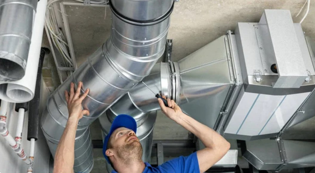
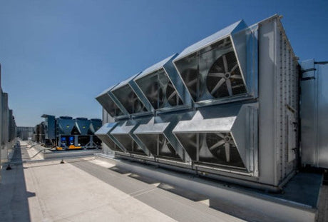
Efficient flow measurement in the air canal is the foundation for energy -efficient building technology and optimal room air quality. In a time of rising energy costs and tighter environmental requirements, the precise wins Flow measurement in HVAC systems (Heating, ventilation, air conditioning technology - HLK) increasingly important for engineers and technicians. This practical guide shows proven measurement techniques, Application examples From various industries (including water treatment) and modern solutions for reliable air commitments in HLK systems. So you will learn how a good one Flow measurement in the air canal can contribute to reducing operating costs and system optimization.
Why is flow measurement in air channels indispensable?
The Flow measurement in the air canal Forms the backbone of modern HLK systems. Without precise air volume flow data, neither energy consumption nor the room air quality can be optimized. The continuous monitoring of the air flows enables system disorders to recognize early, Critical conditions (such as filter deflection or ventilator failure) to be remedied in time and minimize operating costs.
Central benefit aspects in practice:
- Energy -efficient regulation of ventilation and air conditioning systems- avoids unnecessary air exchange and saves heating or cooling energy.
- Compliance with air quality standards in office and industrial buildings- ensures health and comfort.
- Monitoring of the filter performance - Report in good time when filters have to be changed or cleaned.
- Evidence of the plant specification - e.g. compliance with planning values and norms (such as DIN EN 12599) with acceptance and operation.
A modern Flow measurement in the air canal Also helps to recognize clogged filters or defective fans immediately in the system. Especially in Energy -efficient buildings With needs -based ventilation is one precise flow monitoring indispensable in order to actually achieve the planned savings and room air conditions.
The most important measurement principles for air currents (HVAC)
There are different Measurement techniques, to capture the flow speed and the volume flow in air channels. In the following we present the most important measurement principles - each with their functional, advantages and typical areas of application.
1. Thermal flow measurement (Calorimetric principle)
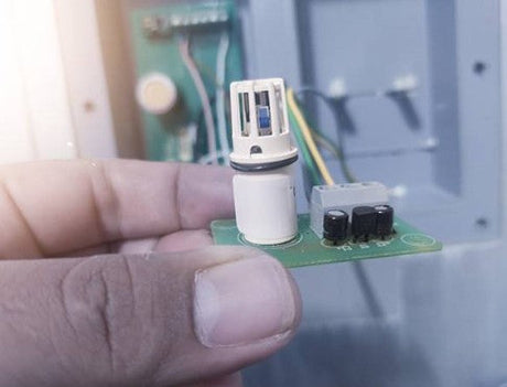
The Calorimetric measuring principle has established itself as particularly reliable for flow measurement in HVAC applications. It is based on the heat -mometry, i.e. the heat transfer between a heated sensor and the pasted medium (air).
How it works: A temperature sensor is constantly heated to a defined temperature, while a second sensor measures the current media temperature. If air flows past the sensor, the air flow cools down the heated sensor - the necessary energy (or the temperature difference between the sensors) is proportional to the flow speed. Modern devices automatically compensate for air fluctuations in the air by regulating the heated sensor for a reference value.
Advantages of thermal flow meters:
- High sensitivity: Measure very low flow speeds reliably from approx. 0.1 m/s.
- High accuracy: Measurement accuracy up to ± 2 % of the measured value can be reached.
- Independence of the installation position: 360 ° measurement capacity, i.e. largely independent of the direction of flow.
- Maintenance -free operation: No moving parts or pollution problems due to encapsulated sensors.
👉 Product recommendation: For demanding HLK applications, Seikom Electronic offers that RLSW®9 volume stream device -A high-quality solution for precise air flow measurements in ventilation systems. This calorimetric measuring device covers an range of 0.1 to 30 m/s (optionally even up to 200 m/s) and is designed for media temperatures up to 350 ° C. Thanks to linear analog outputs (0–10 V and 4–20 mA) and a easily readable LCD display with LED status, this is RLSW®9 Ideal for monitoring and regulating air flows in Industrial plants suitable.
2. Walking wheel anemometer
The Wing wheel anemometer (also shovel anemometer) is a classic mechanical measuring device for flow speeds, which is used especially in medium to higher air speeds. Here a small impact wheel (propeller) rotates in the air flow and the speed is converted into a speed signal.
Properties and advantages:
- Typical measuring range: About 0.5 to 30 m/s flow speed (depending on the device).
- Robustness: Mechanically simple, proven technology with robust structure - also suitable for rough environments.
- Direct display: Many hand-anemometers directly indicate the current flow speed; Suitable for fast Point measurements For review.
- Integration time adjustable: For more detailed results, averaging can be made to compensate for turbulence effects.
- Cost efficiency: A comparatively cheap solution, especially for temporary measurements Or mobile missions, since often no fixed installation is necessary.
- Area of application: Wing wheel anemometers are often used to check ventilation systems, in laboratories or in the field service. In permanently installed systems, they are less common than the thermal sensors because they have moving parts and higher maintenance effort.
3. Different pressure process (storage/pitot tube)
One Further established method This is for aerial power in channels Different printing process. Here, the flow speed is indirectly determined using the pressure difference between dowel pressure and static pressure of the flowing air. Typically come Prandtl’s storage tube (pitot tube) Or use special differential pressure sensors with impact plates.
Functional principle: A pipe with opening contrary to the direction of flow measures the overall pressure (dust pressure), while a side opening or a second line captures the static pressure in the channel. From the pressure difference, the device calculates the Flow speed According to the Bernoulli equation. If the setup is added by several measuring points or an effective pressure probe, the volume flow can also be determined via the sewer cross -section.
Advantages and special features:
- Proven technology: Different pressure measurements have been used for a long time and are described in many standards.
- Simplicity: Sensors are comparatively simple and can often be retrofitted (a hole in the channel for the storage tube is sufficient).
- Area of application: Well suited for High flow speeds and large channel cross -sections. However, very low speeds (<0.5 m/s) can be recorded less precisely.
- Maintenance: Staur pipes have no electronics in the air flow and are insensitive, but they have to be checked occasionally for dirt.
4. Ultrasonic flow measurement
At the Ultrasound flow measurement Acoustic signals are used to determine the flow speed of the air. Two opposite sensors send and receive ultrasound pulses that are influenced by air flow.
Functional principle: The sensors are arranged in such a way that a sound impulse With the current and one Against the current is sent. The air flow causes a minimal term of running time between the two directions - sound with the air flow requires a little shorter than contrary to the direction of the river. From this Term difference Calculate the electronics the average flow speed in the measuring cross section. Modern ultrasound flow meters can also identify the flow direction (forward and backflow) and often measure the media temperature at the same time.
Application advantages:
- Wide measuring range: Typical up to ± 40 m/s flow speed measurable - also suitable for very high speeds.
- Large cross -sections: Can be used for channel diameter up to several meters (e.g. up to 2.5 m or larger), since no installation in the flow cross-section is necessary.
- No mechanical parts: Wear -free and low -maintenance, since only sound signals are used.
- Versatile measurement variables: In addition to the volume flow, some devices also deliver temperature and direction of the current.
Area of application: Ultrasound measuring systems can be found primarily in large ventilation channels, e.g. in Remands, tunneal tests or large industrial plantswhere conventional sensors would be difficult to install. Due to the advanced technology, they are usually more expensive to buy, but offer unique advantages in special applications.
Selection criteria for flow measuring devices
When choosing the right measuring device for the Flow measurement in HVAC/HLK systems different parameters must be taken into account. Each field of application places different requirements - from small climate channels to large exhaust dates in industry.
Important selection criteria at a glance:
- Measuring area of the flow speed: Do you need very low speeds from 0.1 m/s or is it about high currents up to 50 m/s and more? Choose a device that the required Speed area (e.g. 0.1 - 20 m/s or 5 - 50 m/s) reliably covered.
- Media temperature and quality: Note the temperatures in the channel. Standard devices work from approx. -20 ° C to +80 ° C. Special high -temperature sensors are necessary for higher temperatures (hot air, exhaust air from processes up to 350 ° C). Moist, dust or aggressive components of the air can also affect the device selection (robust material, protection class IP67 or similar).
- Channel dimensions and installation conditions: There may not be a large measuring device in very small channels - compact sensors or probes are suitable here that are inserted from the outside. In very large channels (diameter> 1 m), several measuring points or special methods (ultrasound, pitot tube arrays) may have to be used to obtain representative results.
- Desired measuring accuracy: Think about how precisely the measurement must be. For Energy statements or validations Should highly accurate devices (errors <2–3 %) be used. For a pure monitoring task (e.g. fan runs/does not run), a flow guard can also meet with a little less accuracy if costs are saved.
- Signal output and interfaces: Make sure that the measuring device offers compatible outputs for your control or control technology. Analog 0-10 V, 4-20 MA Or digital interfaces (modbus, bacnet) are required depending on the system. The power supply (24 V DC, 230 V AC, etc.) must also fit.
Measuring area and typical channel speeds: Some guidelines for classification here: in Supply air channels The air usually moves from ventilation systems with 2–8 m/s, in Exhaust air channels A little faster (3–12 m/s), main lines reach large systems 5–15 m/s. Industrial suction systems Or process air can have currents up to 30 m/s. These numbers help you choose a device with a suitable measuring range. If the device is too far above the usual area, the resolution suffers at low values; If it is too tight, it reaches its limits at top loads.
Installation and optimal positioning
The Correct installation A flow meter is crucial for precise results. Even the best measuring device delivers incorrect values when it was placed in the channel or were improved improperly. Therefore, note some basic rules for installation:
Correct placement in the channel system
- Consider inlet routes: Air flow should be calmed down and evenly at the measurement point. At least are recommended 5 × pipe diameter straight distance in front of the sensor, better more. After interference, such as narrow arches, branches, fans or flaps, are even approx. 10 × diameter Inlet route advises because there is turbulence.
- Take into account the discontinued line: Behind the sensor should be at least 3 × pipe diameter Just follow the route. It is avoided that the sensor sits directly in front of a further disturbance (such as a curve), which could influence the measurement.
- Position in cross -section: Ideally, the sensor is placed in the middle of the sewer cross -section, where the current is the most representative. In the case of pollution probes, the sensor cap should be approximately to the middle of the sewer. In round pipes, it can make sense to arrange the probe slightly diagonally to minimize the influence of gravity on dirt deposits.
- Note the main flow direction: Many sensors (especially thermal) measure independently of the direction, but it is still advisable to align them according to the intended flow direction (if specified by the manufacturer). This also facilitates the interpretation of markings and possibly directional ads.
Avoid frequent installation errors
- Inadequate sedative routes: If the above -mentioned straight routes are not observed, the current can still be swallowed or unevenly distributed at the measuring point. This leads to significant measuring errors. If necessary, you have to work with flowers (e.g. honeycomb lattice) if no longer straight lines are possible.
- Assembly in unfavorable zones: Avoid installation directly behind arches, throttle valves or fan outlets. There are often there Transverse currents Or rotary components in the air flow that falsify the measurement. Better install a little further away.
- Leckages at the measuring point: Pay attention to a dense implementation when probes are inserted into the channel. Leader can not only influence the measurement, but also lead to air escaping or pulling, which can interfere with the overall system. Use suitable screws or flanges to seal the installation location.
- Wrong immersion depth: The correct immersion depth must be observed in particular in the case of insert sensors. If the sensor is too far out or if it protrudes too little into the air flow, it does not measure representative. Most manufacturers specify how the sensor should be positioned (e.g. tip in the middle of the pipe). Stick to these specifications.
Monitoring and alarm systems (flow guards)
In addition to the continuous measurement of the exact air flow, there are many applications in which it is sufficient, To monitor threshold values - So simply determine whether the current is available or exceeds a minimum value. Come here Flow To use, which raise the alarm if the current or too high current current or high current.
👉 Product recommendation: For the reliable monitoring of minimum or maximum currents in HLK systems, Seikom Electronic offers the Flow guard RLSW®5 F3 to. This sensor works according to the one described above thermal principlebut is primarily as Switch designed. You can adjust individually at which flow speed its relay switches. For example, Minimum air quantities monitor (important for exhaust air systems to pay dangerous substances safely) or Maximum limits set (for example to prevent too strong air flows that waste energy).
Essential features of the RLSW®5 F3:
- Maintenance -free, encapsulated sensor with Thermal measurement principle (no moving parts).
- Adjustable switching thresholds: Flexibly adaptable to the desired minimum or maximum flow.
- Relay output (Wechsler), who can trigger an alarm directly or switch off a system if the flow value is outside the target area.
- Robust housing (type of protection IP67), suitable for industrial environments.
- Operating temperature of the medium up to 90 ° C, which means that warm exhaust air can also be monitored.
Application advantages: Such a flow guard recognizes e.g. Fan failures or filter pollution Very early because these events immediately fall below the threshold value. In an emergency, the device can be one Automatic shutdown Introduction or report to the building management technology to avoid consequential damage. At the same time he wears one Energy -efficient management At-for example by putting a system into stand-by as soon as air promotion is no longer required. Integration into existing controls (PLC or building control system) is easily possible through the standard signal or the relay.
Important norms and standards
In the Flow measurement for air channels Different standards and guidelines apply that should ensure that measurements are comparable and reliable. Depending on the industry and region, different standards can be relevant:
- DIN EN 12599: Ventilation of buildings- test methods for ventilation and air conditioning systems. This standard describes how acceptance and functional tests of HLK systems must be carried out, including volume stream measurements on ventilation through letters and channels.
- DIN EN 16211: Ventilation in buildings-simplified methods for air volume flow measurements. Simplified measurement methods for volume flow in air lines are shown here, which is helpful in practice for quick checks.
- Ashrae 111: (Ansi/Ashrae Standard 111-2008) Practice for Measurement, Testing, Adjusting, and Balancing of Building HVAC Systems. A standard, which is widespread in the United States, that provides practice -oriented instructions for measurements and the setting of ventilation systems.
- ISO 3966 / ISO 7194: International norms that Measuring methods in air channels (in particular by means of a storage ear after the Print differential procedure) define. These are important if it is to be measured according to uniform methods worldwide.
For operators and engineers, compliance with these standards means that the Measurement accuracy and documentation meet certain minimum requirements. Especially for official exams or certifications (e.g. in clean rooms or in the event of occupational safety considerations), it is advisable to orientate yourself to the standards mentioned.
Maintenance of flowers
So that flow measuring devices work precisely for years Regular maintenance and calibration are not neglected. Many modern sensors are low -maintenance, but it is not possible without control - especially since deposits or aging can affect the measured values.
Recommended calibration intervals: One is common annual calibration of the flow meter. In less critical applications (e.g. pure ventilation control without billing), this interval can also be extended to two years. In Safety -relevant or particularly precision -demanding areas (Pure rooms, explosion protection, authorized investments), on the other hand, are sensible for semi -annual reviews. After larger conversions on the system or repairs to the sensor, re-calibrated Re-calibrated in order to have confidence in the measured values.
Consideration measures at an overview:
- Visual inspection: Check the sensor for dirt, dust or damage at regular intervals. For example, thermal sensors can be covered by dust, which changes the heat transfer behavior.
- Electrical connections: Check the cables and plug connections for corrosion or looseness, especially for devices outdoors or in damp environments.
- Functional test: As part of the maintenance, simulate different flow conditions (e.g. by blowing the sensor or reducing the fan speed) and checking whether the output signal or the display reacts plausibly. Flow guards with switching function should have them tested on their alarm (e.g. temporarily changing swells by adjusting to trigger the switching point).
- Documentation: Hold all calibration and test results in writing. Many standards require a calibration protocol. In the event of an error, you can prove so that the device has been properly checked. You can also see over the years whether there are trends (e.g. drifting measured values) that indicate an exchange of the device.
A well -maintained flow measuring device ensures that Your system runs optimally. The little effort of an annual review pays off by avoiding incorrect controls and inefficient operation.
Practical application examples
At the end we look some Practical examples in which flow measurement plays an important role in the air channel - including a look at the water treatment, which is particularly relevant for many of our readers:
1. Energy -efficient building technology: In modern office and administrative buildings, well-thought-out flow measurement concepts enable significant energy savings. One Need -controlled ventilation - Controlled using air quality (CO₂ sensors) and presence- the supply and exhaust air quantities adapt dynamically. A flow sensor continuously measures the volume flow and ensures that air is never promoted more than necessary. The result: up to 30–50 % less ventilation energy consumption And yet a comfortable indoor climate.
2. Water treatment and sewage treatment plants: In systems of industrialists Water and sewage treatment plays a major role - for example, when ventilating the beams in sewage treatment plants or the exhaust air guide from containers and pools. A reliable Flow measurement in the air canal Make sure that enough fresh air is blown up for biological cleaning processes and that the resulting gases may be removed safely. Flow guards often monitor the minimum air flow here to Critical below To recognize immediately - this protects employees and guarantees stable process conditions.
3. Industrial suction systems: In the case of suction systems for dusts, smoke or vapors (e.g. in welding, chemical operations or woodworking systems), a continuous Flow measurement in the exhaust air channel Security relevant. If the air flow falls below a certain minimum speed, dangerous substances can accumulate or accumulate. Therefore, flow guards are used here that trigger an alarm or switch off the system if the extraction is too low. At the same time, volume streams help the suction system energy -efficient to operate - no more suction power than necessary, but always enough for security.
4. Pure space technology: In clean rooms (e.g. semiconductor production, pharmaceutical industry, laboratories), defined air volume flows and pressure differences must be adhered to exactly to ensure the purity classes. The Flow measurement in HLK channels ensures that sufficiently overcapted air is constantly pumped by filters to remove particles from the air. Even small deviations could increase the particle concentration. Therefore, high -precision thermal flow meters are often installed here, and the system drivers regularly check the values as part of quality management.

