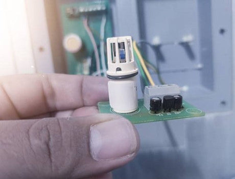
When installing a flow sensor, there are a few things to consider: regardless of whether it is a compact device with a permanently connected electronics or a discontinued sensor with a separate evaluation unit.
In this article we explain what is important in the assembly of a flow sensor to achieve optimal measurement results. The focus is on Calorimetric flow sensors to Monitoring and measurement of gas currents.
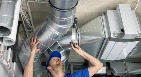
Placement of the flow sensor in the air canal
For a precise measurement result one should Laminar current to be sought. This means that the air should flow past the sensor evenly and without turbulence. Sources for turbulence such as bends, fans, ventilation flaps or narrowing should therefore be avoided. These elements can disturb the current and thus falsify the measurement results. In new systems, such sources of interference can be easily avoided by installing the sensor on a straight section of the channel. In the event of existing systems, it should be considered if necessary whether the sensor is more sensible.
The optimal immersion depth of a flow sensor
A flow sensor should always be installed in the middle of the pipe or channel. This central placement measured the previously mentioned laminar current. The correct placement of the sensor tip is crucial. If in doubt, it is advisable to choose a slightly longer sensor. The rear end of the sensor can easily protrude from the tube or channel as long as the sensor tip reaches its correct place. By choosing a slightly longer sensor, you have some scope for aligning the sensor, the current should not be ideally typical in the middle of the pipe due to a bend, a flap or other obstacle in the pipe.
Installation of the sensor: standing or hanging installation position?
The sensor basically works independently. Nevertheless, there are a few things to consider when installing.
If your application leads to the formation of water vapor, it is advisable to position the sensor upright with the sensor tip. If water vapor forms, it can slowly run down on the sensor. The sensor does not damage this. With a hanging assembly with the sensor tip downwards, the water vapor can drain. This fast temperature change can incorrectly interpret the sensor as a current.
In addition, it plays a role whether the sensor is installed in a horizontal or vertical tube section. The background is the thermal, i.e. the ascent of warm air masses. If the sensor is installed in a vertical tube section, air can be buoyancy, which is registered accordingly by the sensor. This plays particularly in applications in which small air currents are to be monitored or measured as well as in applications in which heated air circulates. If possible, you should therefore always install the sensor in horizontal pipe sections or set the switching point so that small current caused by thermal does not lead to triggering the guardian.
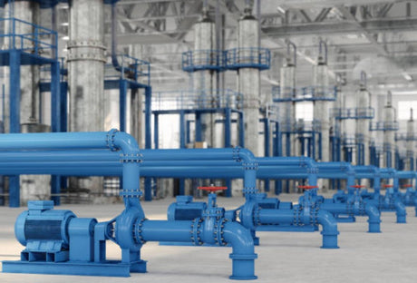
The importance of inlet routes and outlet routes
For each flow sensor, specific inlet routes and outlet routes are given, which should be observed in order to achieve optimal measurement results. The inlet route refers to the straight section of the canal in front of the sensor, while the run -out section describes the section behind the sensor. Typically, the length of the inlet route is between 5 and 10 pipe diameters, while the spout is usually between 3 and 5 pipe diameters. These distances ensure that the current of the medium is sufficiently stabilized before it has reached or left the sensor.
Deviations from the ideal installation specifications: What to do if inlet routes and outlet routes cannot be met?
In many projects, the ideal inlet and run-off routes cannot be observed. This primarily affects existing systems or complex mechanical systems.
The key question here is which measurement task should be met. With simple switching point monitoring - for example to ensure that a minimum air quantity is added to a room or that a fan works in a exhaust system - can often be worked with shorter routes. In this case, measurement accuracy is less critical. However, if it is the exact measurement of the air speed or the volume flow, all manufacturer's information should be observed as possible, since the accuracy is important here.
Modern volume streams such as the RLSW®9 Also offer the possibility to store a calibration factor. If there is a deviation of the measurement result due to the installation position, this effect can be counteracted with the calibration factor with this effect in order to avoid measurement inaccuracies.
Flow measurement directly on the fan - is that possible?
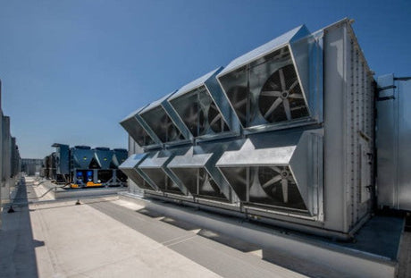
In some applications there are no pipes or channels available for monitoring currents. Typical applications are hazardous substance containers, cooling containers, battery storage or pumping stations. Although the measurement conditions are not ideal, the pure monitoring is whether a fan runs properly without any problems.
You can also find more information on frequent errors in flow monitoring in our white paper: The 6 most common errors in flow monitoring and how to avoid them.
Assembly options: screw -on adapter, assembly fans or directly screw in
Different options are available for installing a flow sensor. From direct screwing in the sensor by means of thread, to the use of a screw -on adapter to the use of an assembly fans
Screw -on
Screwing adapter function like a cable screw connection. Once installed in the air canal, the flow sensor can be easily clamped and fixed with the screw thread. In this way you can easily adapt the immersion depth of the sensor and simply inspect and wait the sensor. There are different types of screw -on adapters, including Standard variants, ATEX-certified explanations For areas at risk of explosion and special adapters for Environments with high temperatures up to 600 ° C.
The installation of this adapter is relatively simple and does not require extensive modifications on the air duct. However, note that you need access to the inside of the air duct to assemble the adapter. This cannot always be given in existing systems.
Mounting fan
A assembly fan is offered stable and secure fastening, especially for larger pipe diameters. Different flange sizes and shapes enable optimal adaptation to the specific conditions of the air canal. This type of fastening also offers high stability and can be used in various industrial applications. For air channels and large pipes, it is recommended Starer Mannenflansch, whereas small pipes flange flange, which ceases to bend the tube.
Direct screw
The direct screwing of the sensor is a cost-efficient method that is particularly suitable for OEM applications. This method also simplifies the maintenance of the sensor because there are no additional fastening elements. Direct screws are particularly suitable in applications in which no high mechanical loads can be expected. Also note that the sensor cable must be turned flexibly. In addition, you also have no scope when positioning the sensor: the immersion depth cannot be changed afterwards.
Summary
The exact compliance with the assembly requirements for flow sensors ensures precise measurement results and a long lifespan of the sensor. Whether central positioning in the tube, avoiding turbulence or choosing the appropriate assembly option - every detail contributes to the optimal functional of the measuring device. If you cannot adhere to the ideal insert and outlet routes, you should analyze the measurement task carefully and, if necessary, compromise.
For more information or specific questions about our flow sensors, please contact our team of experts.